BPUA State Machine Profile
Introduction
Standard UML state-machine notation is a strong starting point for modeling process behavior, but it does not directly express several concepts that are central to Business Process Unit Architecture. In BPUA, a use case is a bounded business-process unit, pages are rendered as a consequence of state, and some states serve as handoff points from one use case to another.
For that reason, this chapter uses a small set of BPUA-specific notation conventions on top of standard UML. This page documents those conventions.
Why a Profile Is Needed
A plain UML state diagram can show states and transitions, but BPUA requires several additional distinctions:
- the boundary of a use case as an execution unit,
- the difference between waiting states and execution transitions,
- the difference between execution transitions and intent transitions,
- states that are final within a use case but may trigger continuation outside that use case.
In BPUA, if business process states are visualized as user interface pages, there is no direct navigation between them. The pages displayed are a consequence of changes in business process states.
Core BPUA Diagram Elements
Use Case Boundary
The outer frame represents the boundary of a single use case. Everything inside that frame belongs to the state machine of that use case. The frame is not merely visual grouping. It indicates the scope within which states, transitions, and handlers are interpreted.
Entry State
An entry state represents the point at which the use case becomes available to the platform.
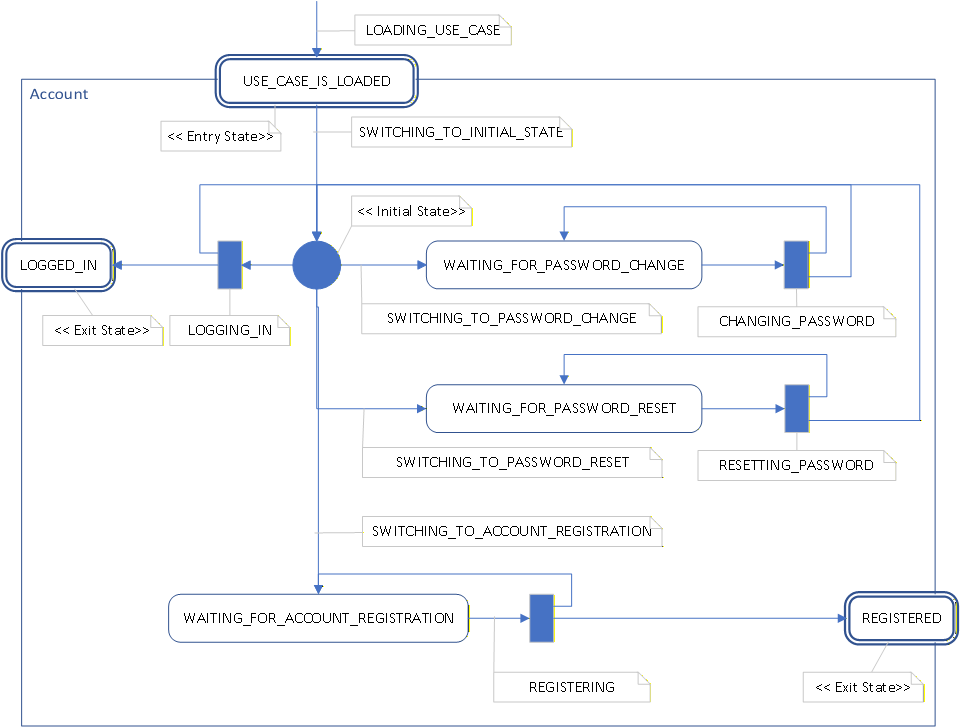
In the Account example, USE_CASE_IS_LOADED serves this role.
It is not yet the interactive working state of the use case.
It marks the point where activation has completed and the use case is ready to move into its initial workflow.
Initial State
The initial state is the first internal working point of the use case. From here the process can move toward its first waiting state or another valid branch. In diagrams, this is typically shown with the standard UML filled circle, but the surrounding BPUA semantics remain important: the initial state exists inside a use-case boundary.
Waiting State
Waiting states represent stable points where the use case expects user input or another external trigger.
Examples include WAITING_FOR_PASSWORD_CHANGE,
WAITING_FOR_PASSWORD_RESET, and
WAITING_FOR_ACCOUNT_REGISTRATION.
Each waiting state usually corresponds to a specific state handler and therefore to a specific page or screen. The page is not the state itself. The page is the presentation selected by the state.
Intent Transition
Intent transitions move the process from one meaningful waiting context to another. They do not merely perform UI navigation. They express an accepted user intention within the business process.
Examples include:
SWITCHING_TO_INITIAL_STATE,SWITCHING_TO_PASSWORD_CHANGE,SWITCHING_TO_PASSWORD_RESET,SWITCHING_TO_ACCOUNT_REGISTRATION.
Although such transitions often lead to a different page being displayed, that page change is the result of a state change handled by the platform. The transition itself belongs to the business process.
Execution Transition
Execution transitions perform business work. They are the active steps that validate input, change data, invoke services, and produce new process outcomes.
Examples include:
LOGGING_IN,CHANGING_PASSWORD,RESETTING_PASSWORD,REGISTERING.
Exit State
Exit states are final states of a use case, but they are not necessarily terminal at the application level. They indicate that the use case has reached a meaningful completion point from which the application may trigger a cross-use-case continuation.
In the Account example, LOGGED_IN and REGISTERED are exit states.
They complete the Account use case,
but the application may use them as handoff points to continue, for example, into a Home use case.
To make this visible in diagrams, exit states may be placed on the boundary of the use case
and may be annotated with the stereotype <<Exit State>>.
This is a BPUA-specific notation convention built on top of UML.
BPUA Stereotypes and Conventions
The following stereotypes and conventions may be used consistently throughout the chapter:
<<Entry State>>- a state reached when use-case activation is complete,<<Initial State>>- the first internal working point of the use case,<<Exit State>>- a final use-case state that may trigger application continuation.
In addition, the naming convention itself may carry meaning:
WAITING_FOR_*- stable process states expecting input,SWITCHING_TO_*- intent transitions that select another waiting context,*ING- execution transitions that perform work.
Account Use Case Example
The following Account diagram illustrates the profile in practice. It shows an entry state, an internal initial state, several waiting states, intent transitions, execution transitions, and two exit states placed on the use-case boundary.
Summary
The BPUA State Machine Profile does not replace UML. It refines UML state-machine notation so that it can express the semantics required by BPUA-based systems.
A standard notation becomes much more useful when it is taught together with the architectural meaning it carries.
By adding a small set of stereotypes, naming rules, and placement conventions, the diagrams in this chapter can describe not only state transitions, but also use-case boundaries, waiting contexts, execution steps, and cross-use-case handoff points.
Table of Content BPUA Chapter Previous: Overview of the Architecture Next: What Is a BPUA Application?
Business Process Programming in .Net
© 2004-2026 Laskarzhevsky Software Inc.
Unless otherwise noted, the content of this website is licensed under the
Creative Commons Attribution 4.0 International License (CC BY 4.0).
Code examples are provided under the MIT License.
You are free to share and adapt the material provided that appropriate
credit is given and any modifications are clearly indicated.
The information provided on this website is for educational purposes only.
The author and publisher make no warranties regarding the completeness
or suitability of the information and are not responsible for any damages
resulting from its use.